

Table of Contents
How plate heat exchangers work. We are going to understand the plate heat exchanger and its entire working process by explaining a simple single-pass plate heat exchanger. They are often referred to as PHEs or HEs in the industry.
Plate heat exchanger is used to transfer heat from a hot fluid to a cold fluid without mixing. Plate heat exchangers are widely used across various industries due to their efficiency and compact design. They are commonly found in the HVAC industry, food and beverage processing, pharmaceutical manufacturing, chemical and petrochemical industries, and power generation plants. PHEs are also used in the automotive sector, pulp and paper industry, water and wastewater treatment facilities, and marine applications. Additionally, they play an important role in the oil and gas industry, renewable energy, as well as in the dairy, textile, and metal processing industries.
For example , in a hydraulic circuit, a plate heat exchanger is used to cool the hydraulic oil. The hydraulic oil gains heat from the hydraulic system, and the heat exchanger transfers this heat from the oil to the cooling water. As a result, the oil becomes cooler, and the water becomes warmer.
Main Component of a Plate Heat Exchanger:
Frame plate & pressure plate, it is thick plate located at front side and back side of the heat exchanger, it is used to hold everything together using tightening boult.
Heat Transfer Plate & Gasket, these are the main components of a plate heat exchanger. The heat transfer plate is a very thin metal sheet used to separate the hot and cold fluids. With the help of gaskets, it forms a thin film of fluid on each side, allowing heat to transfer through the plate.
For more information please visit: Plate heat exchanger basic knowledge.
How It work?
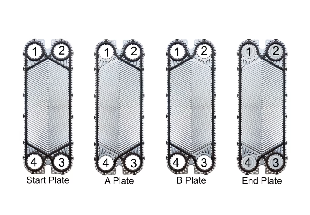
First, we need to understand the plate arrangement
Start Plate:
It is located just after the frame plate and comes with fully closed gaskets, as shown. Because all the ports are closed, no fluid flows toward the heat transfer area on this plate, the fluid is directed to the next plate.
A Plate:
In this plate, left side of the gasket is open, and the right side is closed, as shown. Therefore, the fluid entering from port number ‘1’ will flow through the plate and exit through port number ‘4’ forming a very thin film of fluid across the plate.
B Plate:
In this plate, right side of the gasket is open, and the left side is closed, as shown. Therefore, the fluid entering from port number ‘3’ will flow through the plate and exit through port number ‘2’ forming a very thin film of fluid across the plate.
As required, we use multiple A and B type plates in the plate heat exchanger, which creates alternating hot and cold fluid films throughout the exchanger. Due to the temperature difference between the hot and cold films, heat is transferred through the plates
End Plate:
This plate can be fitted with either A or B type gaskets, but all ports on this plate are closed to prevent fluid from flowing beyond the end plate otherwise the plate heat exchanger start leaking.
For any type of help regarding Heat Exchanger you can Contact Us.
Fluid flow path in plate heat exchanger:
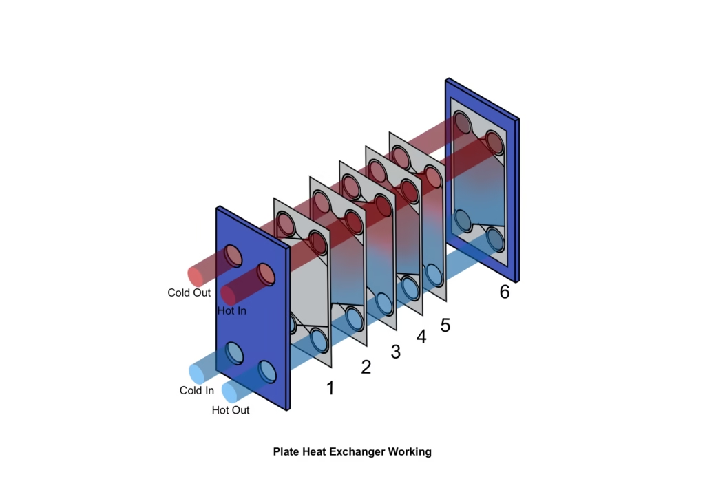
As shown in the image, the upper right port is the inlet for the hot fluid, and the lower left port is the inlet for the cold fluid. The hot fluid enters the plate heat exchanger through the upper right port, while the cold fluid enters through the lower left port. If you look carefully, plate number 1 is the start plate, plate number 2 is an A-type plate, plate number 3 is a B-type plate, plate number 4 is an A-type plate, plate number 5 is a B-type plate, and plate number 6 is an A-type end plate..
When the fluids enter the heat exchanger, all ports in the first plate (Plate 1) are closed, so no fluid flows through this plate—it simply directs the flow to the next plate. In the second plate (Plate 2), both ports on the left side are open, allowing the cold fluid to flow through and form a cold channel. The right-side ports are closed, so no hot fluid flows through this plate.
In the third plate (Plate 3), both left-side ports are closed, so no cold fluid can flow through it. However, both right-side ports are open, allowing the hot fluid to flow through and form a hot channel.
In the fourth plate (Plate 4), both left-side ports are open again, so cold fluid flows through, forming another cold channel. This alternating pattern of cold and hot channels continues throughout the entire heat exchanger many times as needed.
Finally, in the end plate (Plate 6), all ports are closed, so no fluid flows beyond this point. It acts as a sealing end to the exchanger.
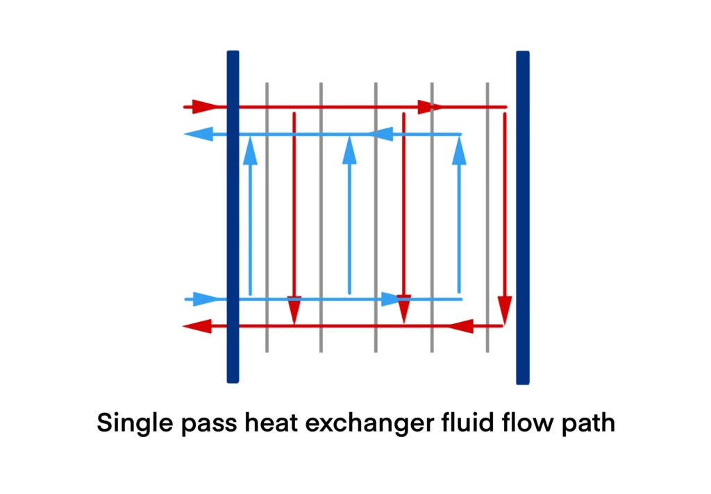
As shown in the side view image of the plate heat exchanger, alternating cold and hot fluid channels are separated by heat transfer plates. Due to the thin metal plates and the temperature difference between the hot and cold fluids, heat is transferred from the hot fluid to the cold fluid through the plates.
The material of the heat exchanger plates and gaskets must be selected based on the operating temperature and the chemical properties of the fluids involved.
Knowledge about heat transfer plate:
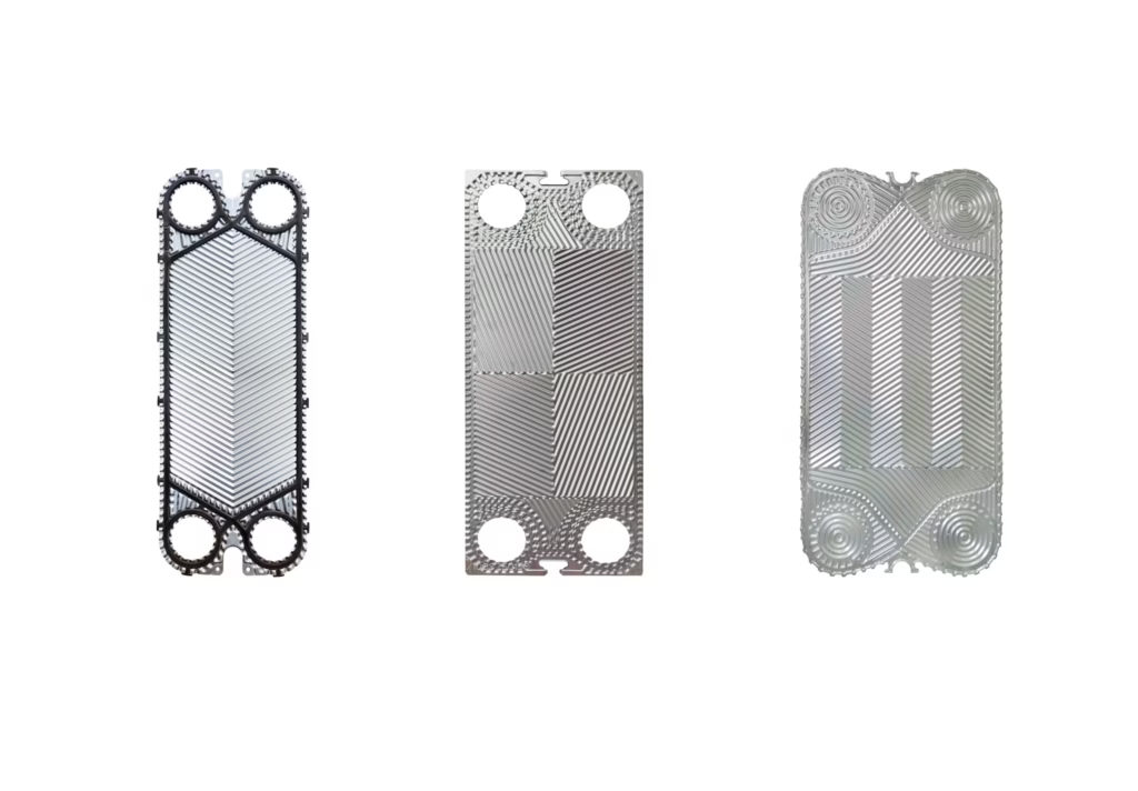
The shape and size of heat exchanger plates can vary based on the design and application of the heat exchanger, as shown in the image with few real-world examples.
Plates are typically made from materials such as stainless steel, titanium, nickel alloys, or Hastelloy. Gaskets are made from various types of rubber, depending on the operating conditions and the chemical compatibility with the fluids.
You can see that the entire plate has a patterned groove, known as corrugation. This corrugation provides structural strength to the plate and increases its pressure-holding capacity. Also, it plays a main role in determining the heat transfer efficiency of the plate and the pressure drop across the heat exchanger. This corrugation creates turbulent flow in the fluid, which enhances mixing and ensures that heat is distributed evenly across the entire plate.
The corrugation is set at a certain angle, commonly referred to as the theta angle, which can be either high (greater than 90 degrees) or low (less than 90 degrees).
Using high-theta plates increases the heat transfer rate due to greater turbulence, but it also results in a higher pressure drop. On the other hand, using low-theta plates reduces both the heat transfer rate and the pressure drop.
By combining high-theta and low-theta plates, the heat transfer rate and pressure drop across the entire plate heat exchanger can be optimized and controlled based on the application’s requirements.